


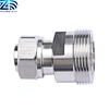

Mini Din Male Straight to MINI DIN Female Connector Adapter
ZD-AD-MM/MF
Mini Din Male Straight to MINI DIN Female Connector Adapter is a RF connector adapter. The center contact is tin bronze with silver plating, the body and outer conductor are brass tri-metal plating, the insulating medium is polytetrafluoroethylene, and the gasket is made of silicone rubber. Characteristic impedance is 50 ohms, frequency range DC - 11GHz, insulation resistance ≥5000MΩ. Low contact resistance, insertion loss ≤0.10dB at 3GHz, VSWR≤1.10 at DC - 3.0GHz. It can withstand ≥500 plug-in and pull-out times, pass mechanical shock and vibration tests, operating temperature - 65℃ - + 165℃, RoHS compliant, used to achieve reliable RF connection from Mini Din straight male to Mini Din female.
Delivery
EXW,FOB,CIF,DAP
minimum order
50 pieces
Supply Ability
1000pieces / Week
Country of Origin
China
Stock Time
7Day
Quantity:
Thismini din rf adapter is a precision‑grade mini din male to female adapter, a high‑reliability rf coaxial adapter also known as 4.3‑10 rf adapter for professional RF interconnection. Engineered with 50‑ohm impedance and DC‑11GHz frequency coverage, it uses tin‑bronze silver‑plated inner contact, trimetal‑plated brass body and PTFE dielectric to maintain superior signal integrity. It achieves VSWR ≤1.10 at DC‑3.0GHz and insertion loss ≤0.10dB @3GHz, paired with high insulation resistance ≥5000MΩ and ultra‑low contact resistance. Validated to MIL‑STD‑202F shock and vibration standards, it supports ≥500 mating cycles, operates from‑65℃ to +165℃ and is fully RoHS compliant. Widely deployed within DAS, IBS infrastructure and microwave test benches, this field‑proven coaxial adaptor delivers consistent, low‑loss connection performance for cellular and microwave engineering systems.
| Mini DIN 4.3/10 Straight Female Connector to MINI DIN male rf adaptor | |||
| Center contact | Tin Bronze / Silver Plating | ||
| Body & Outer Conductor | Brass / Trimetal Plating | ||
| Dielectric | PTFE | ||
| Gasket | Silicon Rubber | ||
| Characteristics Impedance | 50 Ohm | ||
| Frequency Range | DC~11GHz | ||
| Insulation Resistance | ≥5000MΩ | ||
| Contact resistance | |||
| Type | 4.3-10 type male | DIN type female | |
| Center contact | ≤1.5mΩ | ≤0.4mΩ | |
| Outer contact | ≤1.0mΩ | ≤0.2mΩ | |
| Dielectric Strength | 2500V rms | ||
| Working voltage | 1000V rms | ||
| Insertion Loss | @3 GHz | ≤0.10dB | |
| VSWR | ≤1.10@DC~3.0GHz | ||
| Durability (matings) | ≥500 cycles | ||
| Mechanical Shock Test Method | MIL-STD-202F, Method 107G, Test Condition B | ||
| Vibration Test Method | MIL-STD-202, Meth. 204, Cond. B | ||
| Temperature Range | -65~+165℃ | ||
| RoHS | Compliant | ||


